- Hjem
- Products
- Beam-column connections
- Instructions for beam-column connection
Do you want more information and pricing?
Instructions for beam-column connection
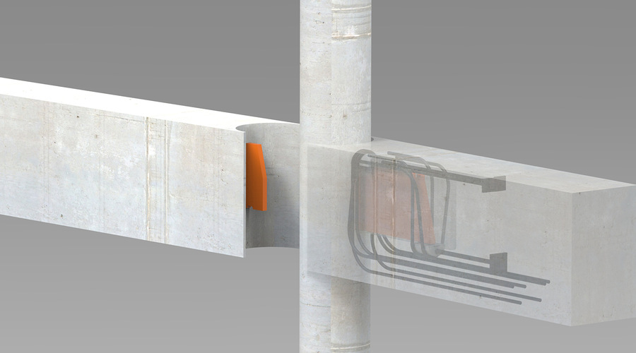
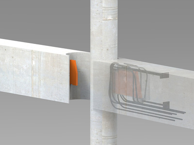
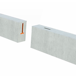
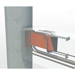
BSF - Beam Column Connection
Corbel free connection between beam-column, beam-beam, beam-wall.
BSF gives possibility for:
- Beam-beam connections.
- Gerber connection.
- Moment rigid connections.
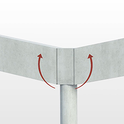
- Beam can be connected angeled against column beam and walls.
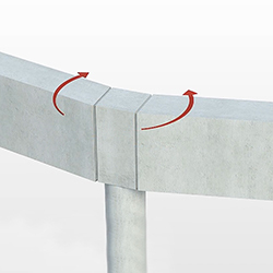
- Elegant olution for round columns.
- The load from the beam is transferred to the inside of the column.
- Efficient installation on construction site.
- Fireprotection after casting.
- Documented and certified solution.
- Documented solution for earthquake requirements (Fly seismic).
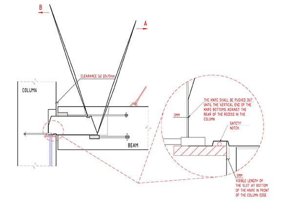
Design principles
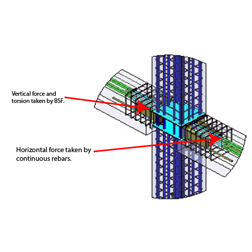
When deployed, the sliding knife cantilevers from the beam into the column. It bears onto the base of the column box at the free end, which induces rotation of the knife. This is resisted by bearing against half-round bearing blocks in the beam (see below). These half-round blocks in turn bear against reinforcement which is not shown in the diagram, but is dealt with later in the guide.
Beam unit: Cast into the concrete beam and must be anchored with specified anchoring reinforcement. Beam-beam unit: Cast into the concrete beam and must be anchored with specified anchoring reinforcement. Column unit: Cast into the concrete column and must be anchored with specified anchoring reinforcement. Knife/sledge: Connect the beam to the column. This is made of solid steel and forms the part of the connection that transfers the load from the beam to the column. Before beam assembly, the knife is retracted and hidden inside the beam unit. | 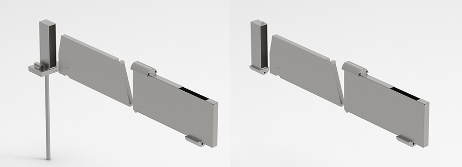 |
Area of use
| Beam - beam, T-connection Connection used to connect two concrete | Beam - beam, Gerber connection Construction method used to connect two | Adapt angels, horizontal Can be adjusted at angels up to 15°. |
  |   |   |
| Adapt angels, vertical Can be adjusted at angels up to 15°. | Double connections BSF can be used in pairs to take heavy vertical | Beam - round column BSF provides an efficient and elegant connection |
 |  |  |
Product serie BSF
All BSF units are marked with a color code and CE number.
BSF 225 kN
| Article no | Description | Capacity | Picture |
|---|---|---|---|
| B 225 | Beam unit | 225 kN | 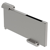 |
| S 225 | Knife | 225 kN |  |
| SF 225 B-B | Beam-beam unit Cast into the concrete beam and anchored with specified anchoring reinforcement. | 225 kN | 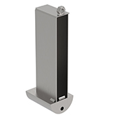 |
| SF 225 | Column unit | 225 kN | 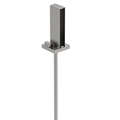 |
BSF 300 kN
| Article no | Description | Capacity | Picture |
|---|---|---|---|
| B 300 | Beam unit Cast into the concrete beam and anchored with specified anchoring reinforcement. | 300 kN |  |
| S 300 | Knife Connecting the beam to the column. This is made of solid steel, and is the part of the connection that transfers the load from the beam to the column. Before beam assembly, the knife is retracted and hidden inside the beam unit. | 300 kN |  |
| SF 300 B-B | Beam-beam unit | 300 kN | |
| SF 300 | Column unit Cast into the concrete column and anchored with specified anchoring reinforcement. | 300 kN |  |
BSF 450 kN
| Article no | Description | Capacity | Picture |
|---|---|---|---|
| B 450 | Beam unit Cast into the concrete beam and anchored with specified anchoring reinforcement. | 450 kN | 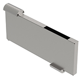 |
| S 450 | Knife Connecting the beam to the column. This is made of solid steel, and is the part of the connection that transfers the load from the beam to the column. Before beam assembly, the knife is retracted and hidden inside the beam unit. | 450 kN |  |
| SF 450 B-B | Beam-beam unit | 450 kN | 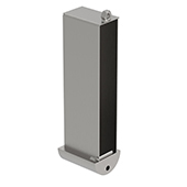 |
| SF 450 | Column unit Cast into the concrete column and anchored with specified anchoring reinforcement. | 450 kN |  |
BSF 700 kN
| Artikkel nr | Beskrivelse | Kapasitet | Bilde |
|---|---|---|---|
| B 700 | Beam unit Cast into the concrete beam and anchored with specified anchoring reinforcement. | 700 kN |  |
| S 700 | Knife Connecting the beam to the column. This is made of solid steel, and is the part of the connection that transfers the load from the beam to the column. Before beam assembly, the knife is retracted and hidden inside the beam unit. | 700 kN | 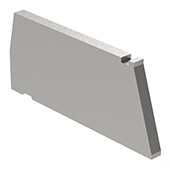 |
| SF 700 B-B | Beam-beam unit | 700 kN | 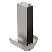 |
| SF 700 | Column unit Cast into the concrete column and anchored with specified anchoring reinforcement. | 700 kN | 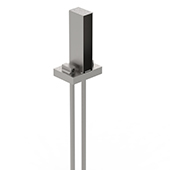 |
BSF 1100 kN
| Article no | Description | Capacity | Picture |
|---|---|---|---|
| B 1100 | Beam unit Cast into the concrete beam and anchored with specified anchoring reinforcement. | 1100 kN |  |
| S 1100 | Knife Connecting the beam to the column. This is made of solid steel, and is the part of the connection that transfers the load from the beam to the column. Before beam assembly, the knife is retracted and hidden inside the beam unit. | 1100 kN |  |
| SF 1100 B-B | Beam-beam unit | 1100 kN | 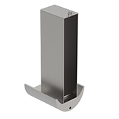 |
| SF 1100 | Column unit Cast into the concrete column and anchored with specified anchoring reinforcement. | 1100 kN | 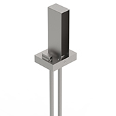 |
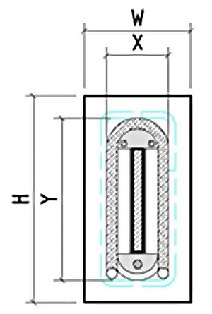
Unit | Max vertical ultimate limit | Approximate absolute minimum beam dimesion to allow for space of the | ||
| (kn) | WXH (mm) | X (mm) | Y (mm) | |
| BSF 225 | 225 | 190 x 370 | 116 mm | 306 mm |
| BSF 300 | 300 | 190 x 420 | 116 mm | 349 mm |
| BSF 450 | 450 | 190 x 440 | 116 mm | 369 mm |
| BSF 700 | 700 | 310 x 500 | 239 mm | 424 mm |
| BS F 1100 | 1100 | 310 x 590 | 239 mm | 518 mm |
Memo/Technical information
| Memo no 501 | BSF, capacities and minimum beam and column dimensions. |  |
| Memo no 502 | BSF, main dimensions. | |
| Memo no 551 | BSF, a short guide to BSF sliding inserts. | |
Reference levels- height difference
Hight differences between the reference level in the beam and column
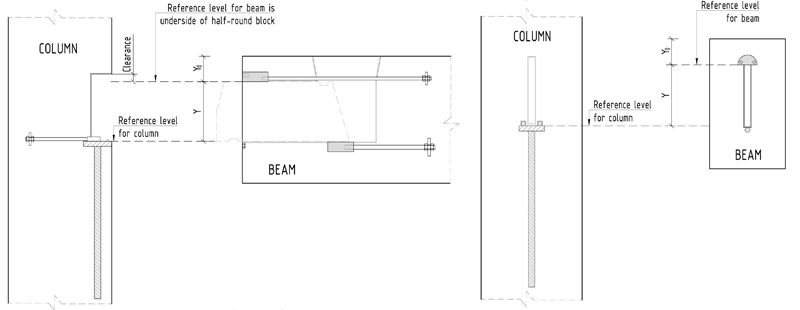
| Unit | Y (mm) | YO (mm) | Y + YO (mm) |
| BSF 225 | 195 | 100 | 295 |
| BSF 300 | 235 | 100 | 335 |
| BSF 450 | 250 | 100 | 350 |
| BSF 700 | 280 | 125 | 405 |
| BSF 1100 | 360 | 125 | 485 |
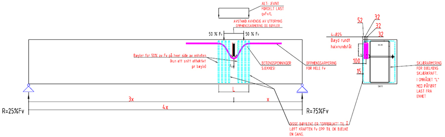
Design principles
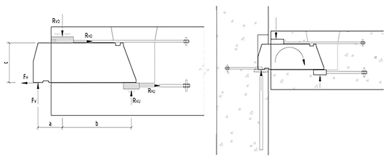
Table 1: Vertical forces (nominal)
The table is for “ideal” values of a, b and c.
| Type | Fv (kN) | a (mm) | b (mm) | c (mm) | RVO (kN) | RVU (kN) |
|---|---|---|---|---|---|---|
| BSF 225 | 225 | 115 | 340 | 195 | 327 | 102 |
BSF 300 | 300 | 125 | 330 | 235 | 456,4 | 156,4 |
| BSF 450 | 450 | 152,5 | 432,5 | 250 | 660,7 | 210,7 |
| BSF 700 | 700 | 165 | 420 | 280 | 1068 | 368 |
| BSF 1100 | 1100 | 206 | 704 | 360 | 1557 | 457 |
Table 2: Vertical forces (maximum)
Larger forces arise when including unfavorable tolerances on location of anchorage reinforcement (± 5mm) as well as construction site deviation (10mm).
| Unit | Fv (kN) | a (mm) | b (mm) | c (mm) | RVO (kN) | RVU (kN) |
|---|---|---|---|---|---|---|
| BSF 225 | 225 | 130 | 330 | 195 | 340,2 | 115,2 |
| BSF 300 | 300 | 140 | 320 | 235 | 475,3 | 175,3 |
| BSF 450 | 450 | 167,5 | 422,5 | 250 | 681,7 | 231,7 |
| BSF 700 | 700 | 180 | 410 | 280 | 1103 | 403 |
| BSF 1100 | 1100 | 221 | 694 | 360 | 1587 | 487 |
For calculation, use memo BSF Calculating XL.
More info, see memo no. 551 and 521.
| Memo no 552 | BSF, production | |
| Memo no 521 | BSF, design of reinforcement | |
| BSF Calculations |  |
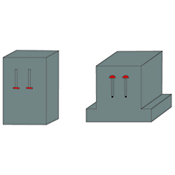
Standard reinforcement - Beam
e.g.: Reinforcement in beam ends BSF 225 with ultimate load 225 kN
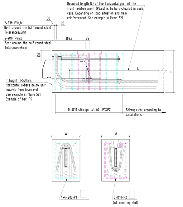 | The amount of reinforcement and final shape in several of the bars must be determined in each case. This can be done accordance to procedures given in Memo. Concrete Quality C35 and beam dimension: W × H = 300 × 450 is used in the example. This beam dimension corresponds approximately to minimum beam cross-section in order to exploit the unit’s capacity. For more information see memo 522a-e. |
| Memo no 522a BSF 225 | BSF 225, reinforcement in beam end | |
| Memo no 522b BSF 300 | BSF 300, reinforcement in beam end | |
Memo no 522c BSF 450 | BSF 450, reinforcement in beam end | |
| Memo no 522d BSF 700 | BSF 700, reinforcement in beam end | |
| Memo no 522e BSF 1100 | BSF 1100, reinforcement in beam end | |
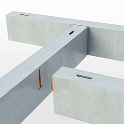
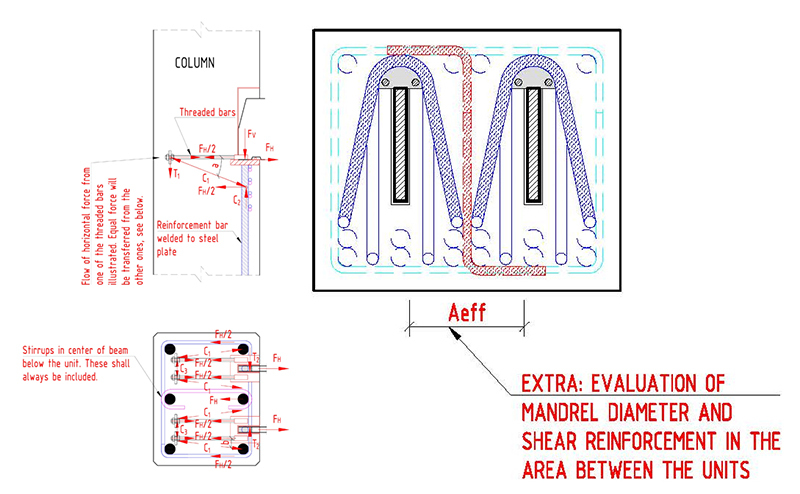
Standard reinforcement - Column
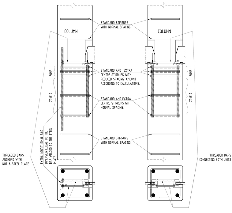 | The figure illustrates the recommended principal reinforcement localy to the column unit. A portion of the vertical force will spread into the column thru the reinforcement bar welded to the bottom of the steel plate, while the remaining force will go into the column thru distributed concrete stress underneath the steel plate. Splitting forces will occur due to horizontal spreading of the forces into the cross section of the column. The amount of reinforcement in Zone 1 can be calculated in accordance with Memo 521. An example of the |
| Memo no 521 | BSF, design of reinforcement. | |
| Memo no 523 | BSF, example reinforcement pattern in column | |
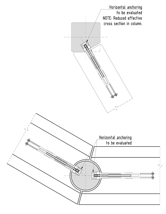
Standard reinforcement- horizontal anchoring
| Memo no 502 | BSF, main dimensions | |
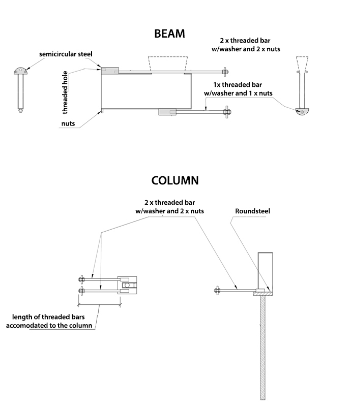
1. BSF (Beam-column connection)
| Unit | Threaded bar | Nuts and washers | Pole | Nuts and washers |
| BSF 225 | 2 x M12 | 2 x 50 x 50 x 8 4 x M12 8.8 | 1 x M16 | 1 x 70x70x10 2x M16 8.8 |
| BSF 300 | 2 x M12 | 2 x 50 x 50 x 8 4 x M12 8.8 | 1 x M16 | 1 x 70x70x10 2x M16 8.8 |
| BSF 450 | 2 x M16 | 2 x 70x70x10 4 x M12 8.8 | 1 x M16 | 1 x 70x70x10 2x M16 8.8 |
| BSF 700 | 2 x M16 | 2 x 90x90x12 4 x M20 8.8 | 1 x M20 | 1 x 90x90x12 2x M20 8.8 |
| BSF 1100 | 2 x M24 | 2 x 110x110x15 | 1 x M24 | 1 x 110x110x15 2 x M24 8.8 |
2. B (Beam-unit)
| Unit | Threaded bar | Nuts and washers |
| B 225 | 2 x M12 | 2 x 50 x 50 x 8 4 x M12 8.8 |
| B 300 | 2 x M12 | 2 x 50 x 50 x 8 4 x M12 8.8 |
| B 450 | 2 x M16 | 2 x 70 x 70 x 10 4 x M16 8.8 |
| B 700 | 2 x M20 | 2 x 90 x 90 x 12 4 x M20 8.8 |
| B 1100 | 2 x M24 | 2 x 110 x 110x15 4 x M24 8.8 |
3. SF (Column-unit)
| Unit | Threaded bar | Nuts and washers |
| SF 225 | 2 x M12 | 2 x 50x50x8 4 x M12 8.8 |
| SF 300 | 2 x M12 | 2 x 50x50x8 4 x M12 8.8 |
| SF450 | 2 x M16 | 2 x 70x70x10 4 x M16 8.8 |
| SF 700 | 2 x M20 | 2 x 90x90x12 4 x M20 8.8 |
| SF1100 | 2 x M24 | 2 x 110x110x15 4 x M24 8.8 |
4. SF B-B (Beam-beam-unit)
| Unit | Threaded bar | Nuts and washers |
| SF 225 B-B | 2 x M12 | 2 x 50x50x8 4 x M12 8.8 |
| SF 300 B-B | 2 x M12 | 2 x 50x50x8 4 x M12 8.8 |
| SF450 B-B | 2 x M16 | 2 x 70x70x10 4 x M16 8.8 |
| SF 700 B-B | 2 x M20 | 2 x 90x90x12 4 x M20 8.8 |
| SF1100 B-B | 2 x M24 | 2 x 110x110x15 4 x M24 8.8 |
Beam - beam, T-connection
Beam cross-section and secondary beam suspension point in the longitudinal direction of the main beam will vary. This may produce different varieties of force once the main beam and the exact load bearing behavior must be assessed in each case. This will vary depending on the geometry of the compound and may arise at the transmission which is not covered by example in the calculations.
For more information, see memo 526.
| Memo no 526 | BSF, design of reinforcement T-connection beam-beam | |
Beam - beam, Gerber-connection
This section deals with BSF used for beam-beam joints on long beam spans (Gerber joints). Reinforcement of the beam end with a simple BSF knife is given in memo 521, so only reinforcement of the beam end with a simple BSF beam box is dealt with here. As beam geometry, concrete quality and load application will vary from case to case there may be aspects of the load transfer that are not covered in this memo.
For more information, see memo 525.
| Memo no 525 | BSF, design of reinforcement cantilivered beam-beam | |
Double connections
As an alternative for large connections, it is possible to use BSF in pairs.
For more information, see memo no 524 and 550.
| Memo no 524 | BSF, design of reinforcement, units used in pairs | |
| Memo no 550 | BSF, practical advice for units in pairs | |
Diagonal connections
For more information, see memo no 508.
| Memo no 508 | BSF connection solution | |
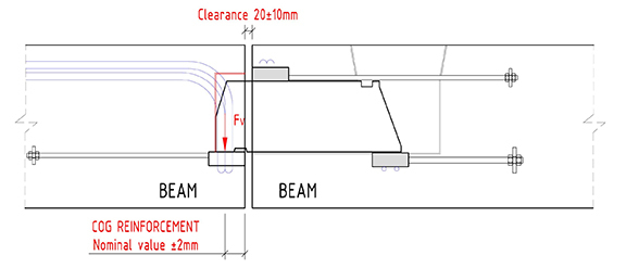
Fire protection, corrosion and winter conditions
The sides and bottom perimeter of the space between the beam end and the column can be sealed with a
backing strip, and the joint concreted. If it is desirable, a fire resistant sealant can be used to cover the backing
strip. Alternatively, the backing strip can be removed.
For more information, see memo no 509.
| Memo no 509 | BSF, winter conditions fire protection & corrosion. |  |
Installation
Torsion – propping. More info, see memo no. 505. Temporary support. Must be calculated in each individual case. |  |
Vertical position of the beams. More info, see memo no. 541. Pulley for adjustment of the beam. |  |
Adjustment of joints. More info, see memo no. 540. | |
Filling and sealing of joints. More info, see memo no. 540. | 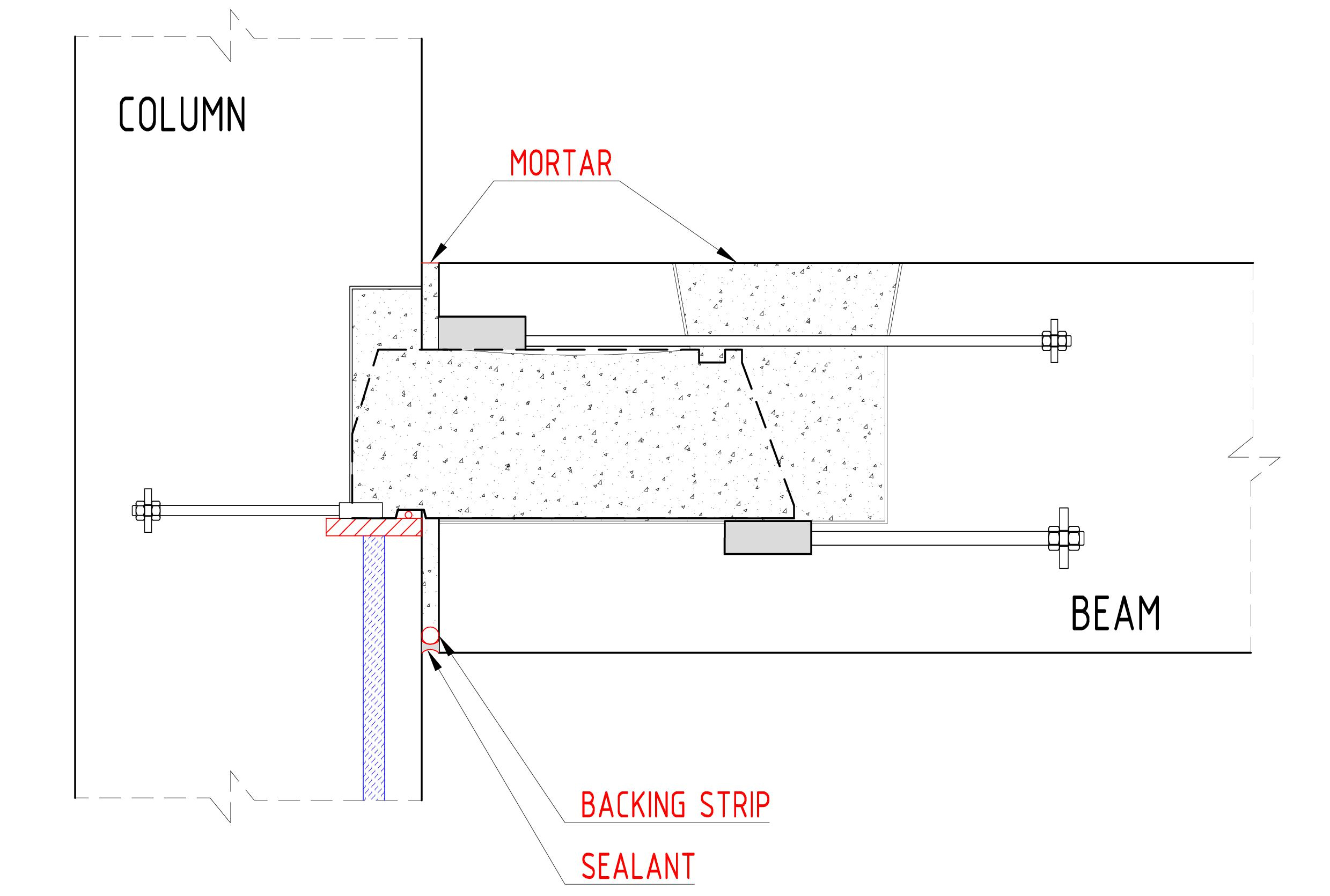 |
For more information about installation, see memo/technical information:
| Memo no 505 | BSF, torsion | |
| Memo no 540 | BSF, installation on site and sealing of joint | |
| Memo no 541 | BSF, plumb position of beams | |
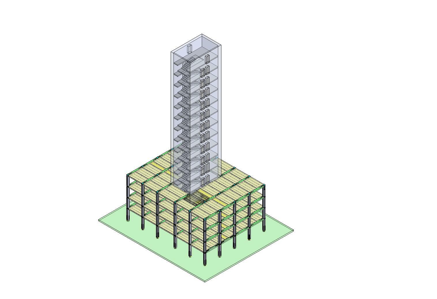
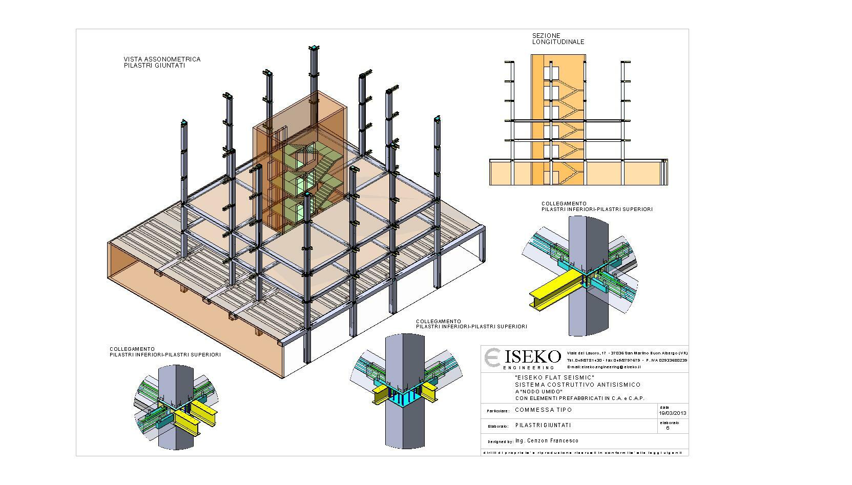
Fly Seismic - solutions for earthquake | |
|  |
Area of use
Commercial buildings/office with Fly Seismic.
 |  |
The system can be used in high buildings.
 | 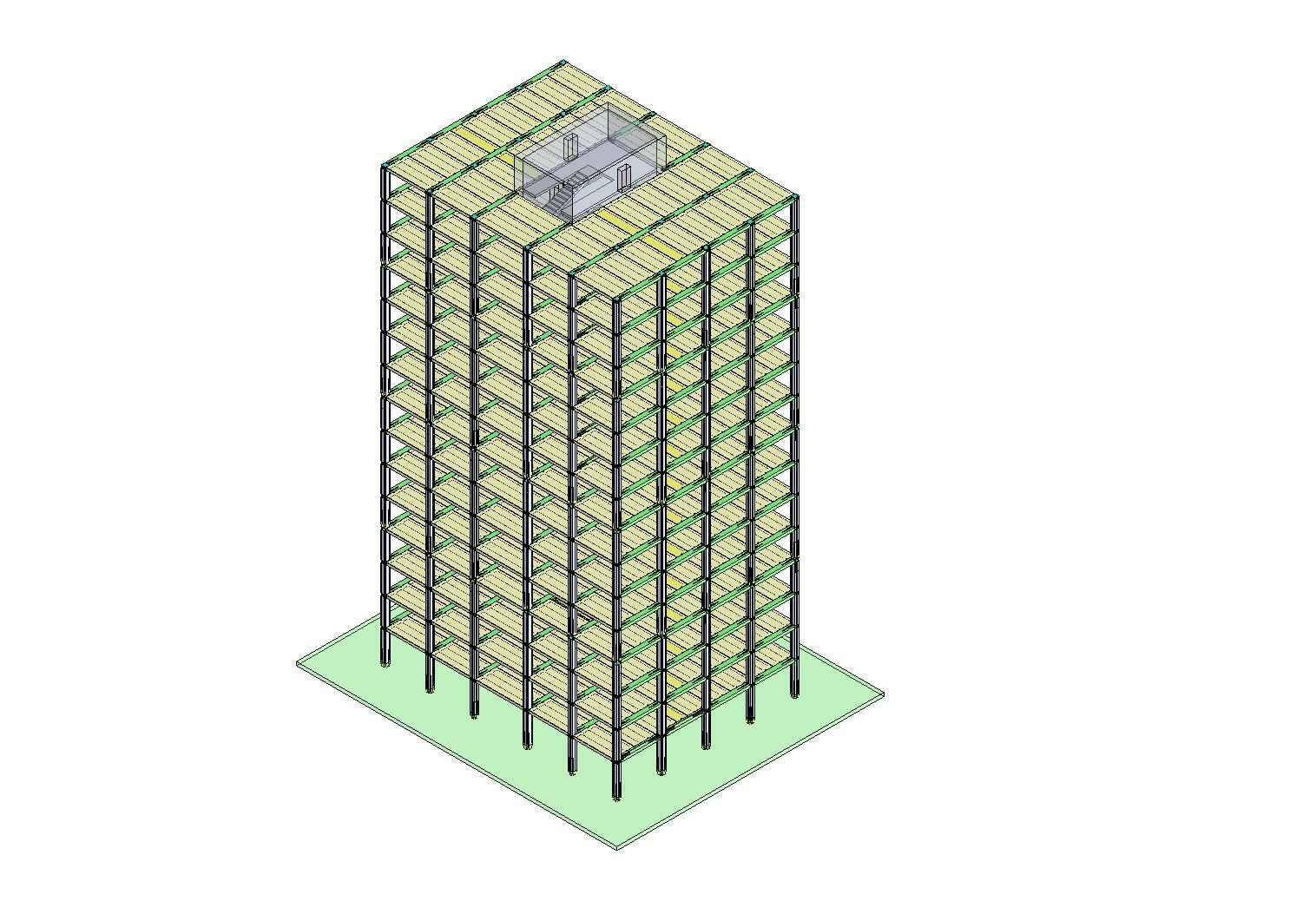 | 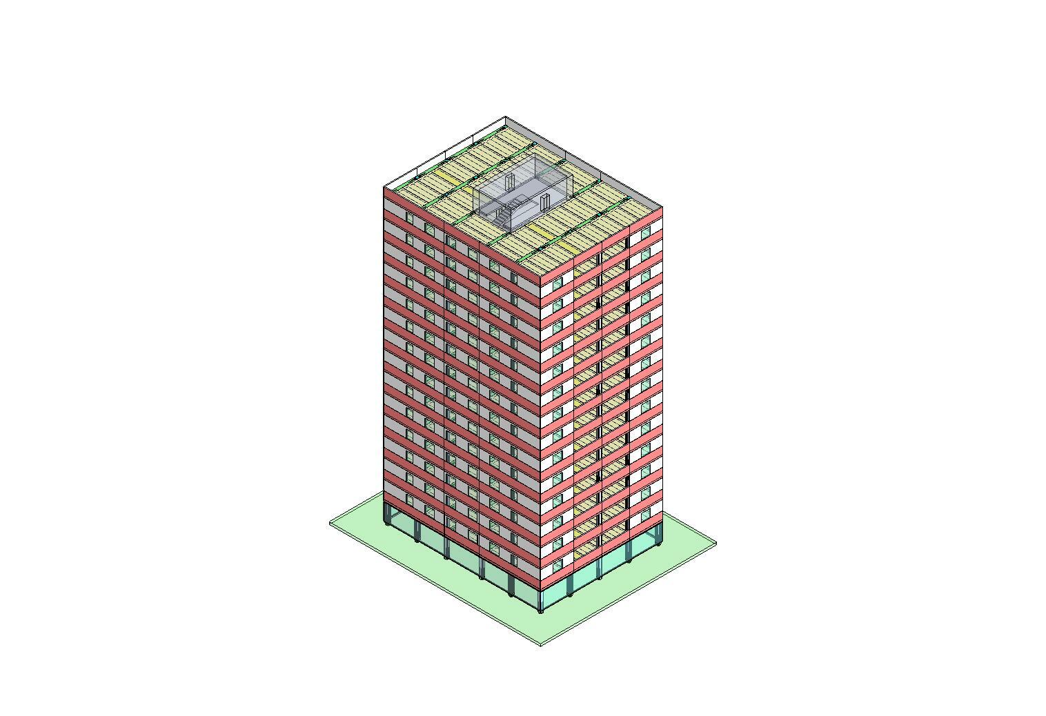 |
Fly Seismic can be used in apartment buildings.
 | 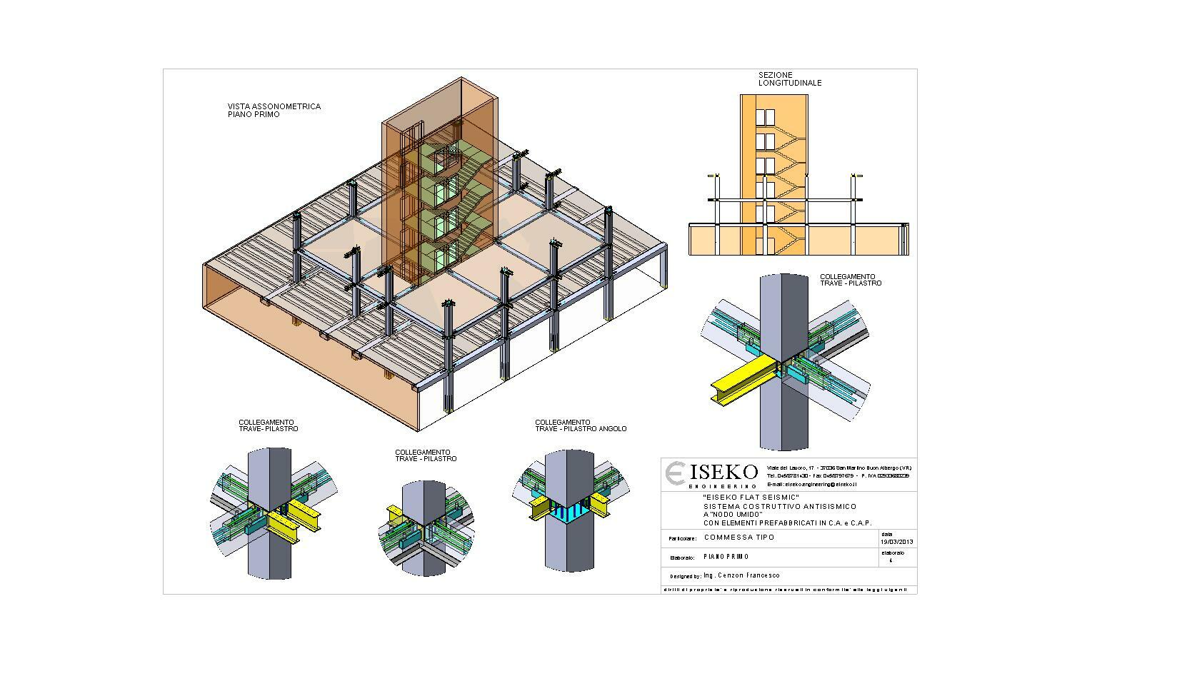 |  |
Brochuresfor downloading