Do you want more information and pricing?
IC solutions for earthquake and stairs in buildings
- IC solutions for earthquake and stairs in buildings
iC has supplied the pre-cast industry with TSS connections for use in landings for decades. These connections are designed to carry static vertical loads, but during a seismic event, additional horizontal forces will occur.
A report /1/ prepared by Des Bull after the 2011 Christchurch earthquakes, is related to the behaviour of stair and ramps in multistorey buildings during an earthquake. The report addresses the problems with “interstorey drift” and constraining forces. The report made iC interested in the subject.
To deal with the interstorey drift, iC has chosen a solution where all stairs are free to slide at the bottom. With this premiss as a governing design principle, The Norwegian company Dr.techn. Olav Olsen was engaged to investigate the suitability of the TSS Connections in earthquake areas /3/. The study can be summarized in three main parts:
- Identify the relevant requirements in the governing seismic design codes in USA, Europe, New Zealand, and China.
- FEM analysis to evaluate the behavior of the TSS 101 connection and ensure it satisfies the demands.
- A parameter study on a multistory building subjected to earthquake. The parameter of the study was the level of ground constant acceleration values, ranging from 0.47g to 3.0g, and the height of the building ranging from 3 to 20 stories. Analyses were undertaken by the computer programs Abaqus and ETABS. The structural response in terms of behavior and forces in the TSS 101 during a seismic event was calculated.
An additional report /2/, also prepared by Dr.techn. Olav Olsen further summarizes the iC solution, and the conclusions from the work forms the basis for iC’s earthquake solution:
- TSS 101 demonstrates a behavior which puts it within the scope of the seismic design standard.
- The parametric study gave design forces well below the capacity of the TSS 101. Because the strong axis of the connection is directed in the horizontal plane it is most probably the design in ultimate limit state (vertical loads) which dimensions the connection. A conclusion on the size of the seismic forces for all kind of situations cannot be formed based on the result from the study, but the study gives a good indication of the expected forces.
The information in this memo is in large parts entirely taken from /2/ and /3/ without direct reference to these reports in the further text.
The dynamic system is simplified due to the sliding solution at the bottom of the stair, preventing constraining forces. During an earthquake, one landing, together with the connected stair, will follow the displacement and acceleration of the wall, at the level of the landing connections. Thus, the dynamic forces may often be
calculated in accordance with simplified formulas.
Dr.techn. Olav Olsen has developed a spreadsheet calculating the forces on the iC connections, when the PFA (Peak Floor Acceleration) is known. The spreadsheet is available for download at iC’s homepage. A user guide is found in Memo 71, together with a simplified method for calculation of PFA. The theory for calculation of the occurring forces in the different connections are also outlined.
Irregular and complex structures may require more sophisticated evaluations to find more precise values of the forces.
ISSUES RELATED TO EARTHQUAKES
RELATIVE DISPLACEMENT BETWEEN STORIES
Different Building Standards vary regarding how much buildings can move, but this can be up to 3% of the
height of the building. Therefore, if a building is 200 metres tall, it can move laterally +/-6 metres at the top.
Among other concerns, this movement can have serious consequences for the stairs in the building.
The difference in horizontal displacement between two stories can create a significant change to the length of
the diagonal line spanned by the stairs.
Figure 2 illustrates a straight stair with a mid-height landing. With a typical story height of 3 metres, the
horizontal distance between the anchorage points can vary +/- 90mm (3000mm x 3%).
In one deformation cycle, the relative displacement between stories causes the stair to compress, which
potentially causes plastic (permanent) deformation of the stair. In the next cycle the span length of the stair
increases which may result in an insufficient support width of the stair and the stair collapses.
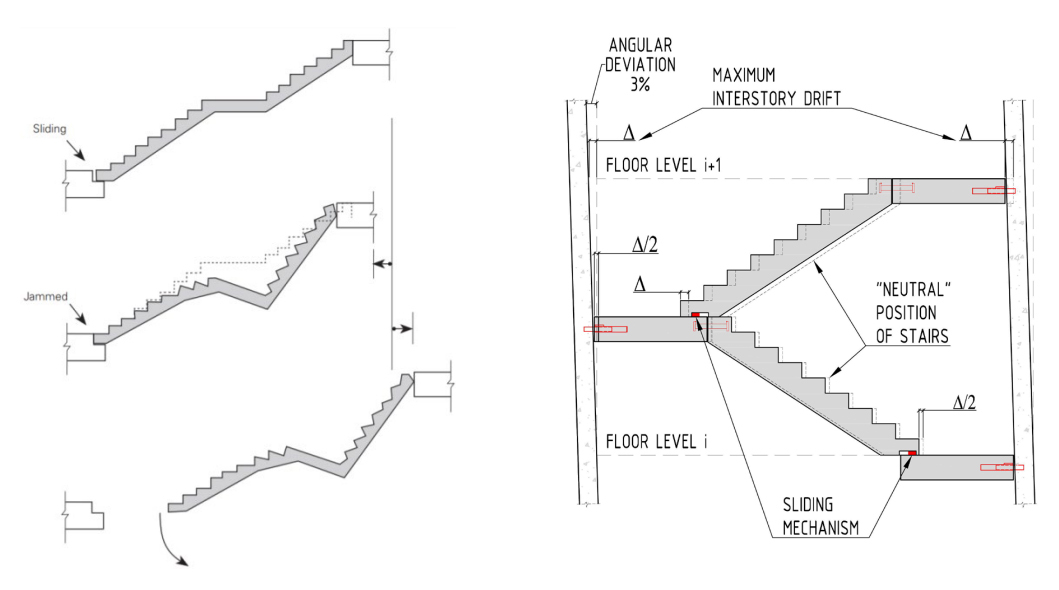
Figure 2: Relative displacement between stories gives a permanent shortening followed by a collapse /1/.
Figure 2, right side, illustrates a typical stair shaft with “scissor” stairs, where the stair turns back 180 degrees
at the mid-height landing. Assuming a storey height of 3m, means the distances between the supports may
vary +/- 45mm (1500mm x 3%). The sliding mechanism at the bottom of the stair must allows for the relative
displacement.
iC SOLUTION – ALTERNATIV A
iC recommends casting one stair and one landing together, as illustrated in Figure 3. Remark that the stair is
placed with a distance to the shaft parallel to the stair direction. This is done to account for the relative
displacement between stories.
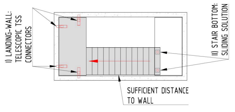
Figure 3: One stair and one landing casted together as one unit – recommended solution.
I) The connection between the wall and the landing can either be TSS 101, or TSS 102. The two front
connections are supported on the sidewalls, while the two rear connections are rotated 90 degrees and
supported on the end wall. The vertical and horizontal resistance for the unit is calculated in /3/, and referred
in Figure 4. Note: the capacity cannot be fully utilized in both directions for combined loads. Forces have to be
combined according to the relevant design code.
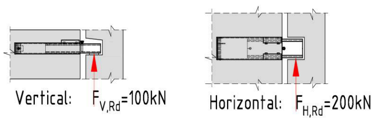
Figure 4: Ultimate resistance for TSS 101 units, ref /3/.
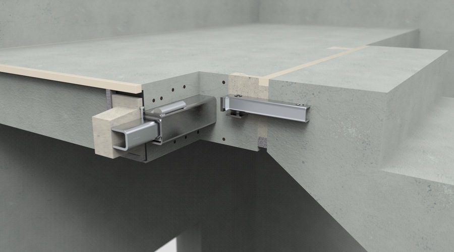
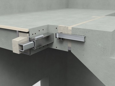
II) The stairs can slide at the support points at the lower landing. A Teflon cladded recess slides on two RHS
profiles bolted to the landing. The free space between the RHS profiles and edge of the recess allows for the
relative displacement.
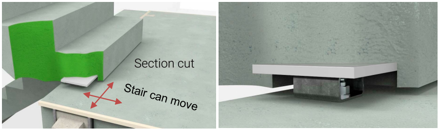
Figure 5: Sliding mechanism at bottom of stair.
For one landing and one stair casted together, the following iC units are required, see Table 1:
| Position | Unit | Picture | Number of parts |
| CAST INTO UPPER LANDING | ALTERNATIVE UNITS TSS 101 | 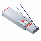 | 4 pcs |
| CAST INTO UPPER LANDING | ALTERNATIVE UNITS TSS 102 | 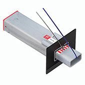 | 4 pcs |
| CAST INTO BOTTOM OF STAIR | EQ plate 200x200 | 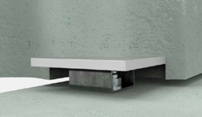 | 2 pcs |
| BOLTED TO LOWER LANDING | EQ RHS 80x40 | | 2 pcs |
iC SOLUTION – ALTERNATIV B
Alternative B is identical to solution A with respect to support of landing and use of sliding solution at bottom
of stair. However, in this alternative the stair and landing are casted separate, and the final connection between
the two parts is done at site.
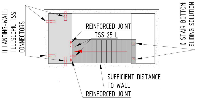
Figure 6: Stair and one landing casted separate.
The TSS 25 L units are used for lifting and height adjustment of the stair at site, but not for transfer of
earthquake forces. The earthquake forces are transferred in separate reinforced joints. This is illustrated in
Figure 7. Note, the iC spreadsheet can calculate the forces in the joints, but the required reinforcement is not
part of the delivery.
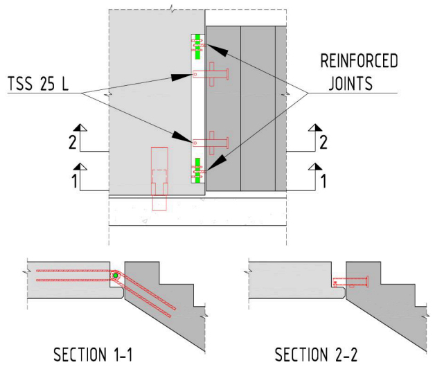
Figure 7: Connections between stair and landing.
For one landing and one stair, casted together, the following iC units are required, see Table 1:
| Position | Unit | Picture | Number of parts |
| CAST INTO UPPER LANDING | ALTERNATIVE UNITS TSS 101 |  | 4 pcs |
| CAST INTO UPPER LANDING | ALTERNATIVE UNITS TSS 102 |  | 4 pcs |
| CAST INTO TOP OF STAIR | TSS 25 L | 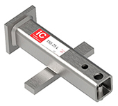 | 2 pcs |
| CAST INTO BOTTOM OF STAIR | EQ plate 200x200 | | 2 pcs |
| BOLTED TO LOWER LANDING | EQ RHS 80x40 | | 2 pcs |
Technical information download
Seismic zones TSS - RVK
| Memo no | Name/download | Format | |
|---|---|---|---|
| Calcyl, Earthquake. | Excel |  | |
| Des Bull | Des Bull Report. |  | |
| Analyses of stairwells performace and damage during Wenchuan earthquake. | | ||
| Memo no 70 | Memo 70 i C SOLUTION FOR EARTHQUAKE AND STAIRS 2 | | |
| Memo no 71 | iC solution for earthquake and stairs spreadsheet. | | |
| Memo no 72 | iC solution for earthquake and stairs additional reinforcement. | |